I/O Circuit Connection diagram
* Download CAD file or product manual for larger image/text and more detail.
I/O circuit
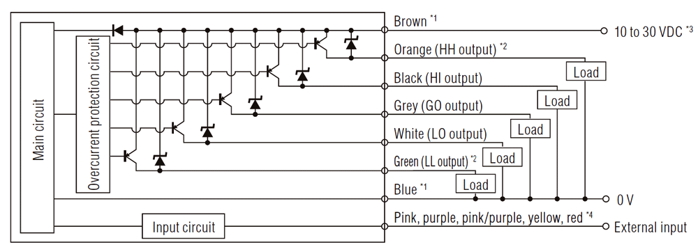
*1 Brown and blue are applicable only to main units (GT2-71N/71P/71CN/71CP/71MCN/71MCP/75N/75P). Not to expansion units (GT2-72N/72P/72CN/72CP/76N/76P).
The connector type expansion unit (GT2-72CN/72CP) is not connected to the internal circuit.
*2 The orange and green cables are used as analogue output cables for the analogue type amplifier unit (GT2-71MCN/71MCP).
For details, refer to the analogue output circuit diagram.
*3 20 to 30 VDC when expansion unit is connected or for the analogue type amplifier unit (GT2-71MCN/71MCP).
*4 For details on external input, refer to the external input circuit diagram.
External input circuit
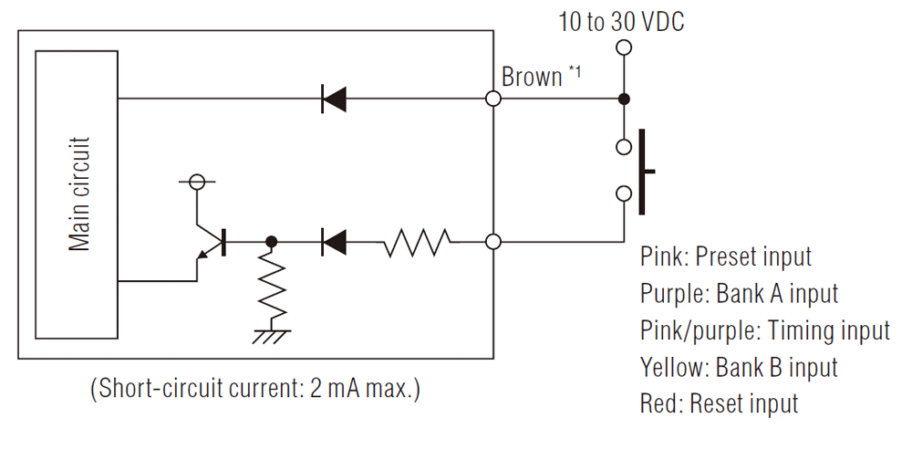
*1 Brown and blue are applicable only to main units (GT2-71N/71P/71CN/71CP/71MCN/71MCP/75N/75P). Not to expansion units (GT2-72N/72P/72CN/72CP/76N/76P).
The connector type expansion unit (GT2-72CN/72CP) is not connected to the internal circuit.
*2 The orange and green cables are used as analogue output cables for the analogue type amplifier unit (GT2-71MCN/71MCP).
For details, refer to the analogue output circuit diagram.
*3 20 to 30 VDC when expansion unit is connected or for the analogue type amplifier unit (GT2-71MCN/71MCP).
*4 For details on external input, refer to the external input circuit diagram.