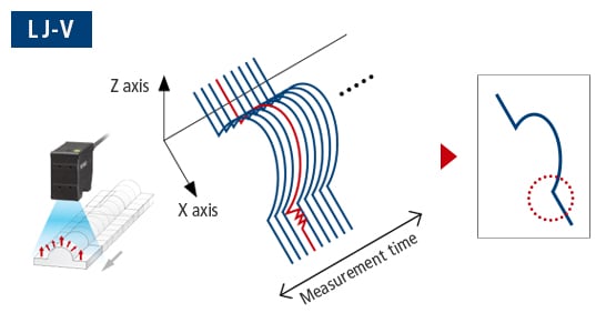
Imaging capability of light-receiving element
The main reason to be aware of the imaging capability of the light-receiving element is because there is no specification that defines such a capability.
This section introduces important factors beyond specifications that should be considered when selecting an inline 2D/3D laser scanner.
Measuring targets with various colors
For 2D/3D laser scanners, an optimal light-receiving element has a wide dynamic range, and is capable of accurately detecting both weak and strong light (without saturation).
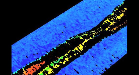
Comparison ExampleWelding Inspection of Electronic Components
Measurement with a narrow dynamic range
Reflection from the weld has not been detected correctly.

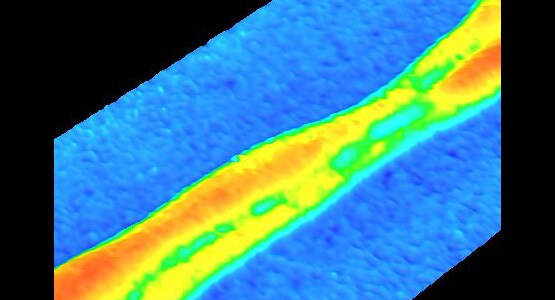
Measurement with a wide dynamic range
We are able to detect welds correctly.
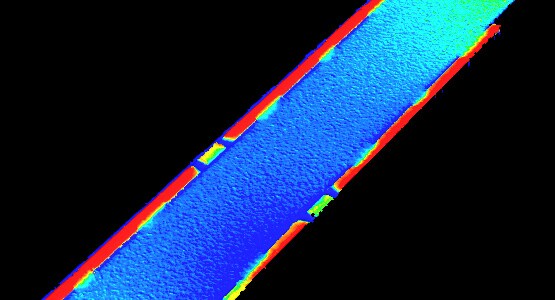
Comparison ExampleSealant Height and Volume Inspection
Measurement with a narrow dynamic range
Reflection from the curved surface causes inconsistent detection.
Measurement with a wide dynamic range
The slope can also be detected stably.
Capturing targets with detailed shapes
If the imaging capabilities of the CMOS are the same, using a shorter interval for the data will allow the target to be captured in greater detail.
However, if the CMOS imaging capability is low—for example, if detection of areas with a low amount of reflected light is difficult—using a shorter data interval will still result in situations like the following.
- Selection Point
A CMOS with advanced imaging capabilities is essential for accurately capturing detailed appearances of fine shapes.
- Selection Point
Use of shorter data intervals is recommended in situations with similar CMOS imaging capabilities.
Speed
For inline applications, the following three aspects are important factors for the sampling speed of the 2D/3D laser scanner.
- Measurement range
- CMOS imaging capability /
Detailed profile measurement
- Data stability
Measurement range
As described in “2. Actual measurement range”, increasing the speed may result in a narrowed measurement range or data thinning.
Verification of whether the required conditions can be met at the desired sampling speed is required beforehand.
CMOS imaging capability / Detailed profile measurement
As the sampling speed increases, the exposure time per sampling becomes shorter.
Care must be taken when measuring targets with low reflectance, dark targets, or targets with sloped surfaces.
As with measurement of detailed shapes, use of high-speed sampling carries the risk of detection becoming impossible for some locations.
Data stability
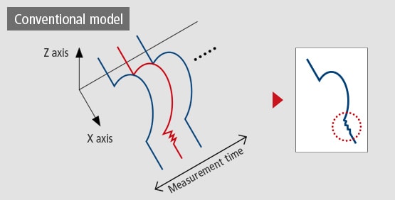
As outlined below, filter processing such as averaging is performed with high-speed sampling in order to stabilize the data.
Using a greater number of data filter processes will provide even greater data stability, so it could be said that higher sampling speeds provide greater stability.
Stabilized Measured Values!
- RESULT OF AVERAGING 3 PROFILES
With conventional models, measurement stability was limited due to insufficient sampling speeds necessary to hit the required cycle times.
- RESULT OF AVERAGING 720 PROFILES
The LJ-V Series provides significantly higher profile stability by utilizing ultra-high-speed sampling as much as 240x faster than conventional models. This allows for profile averaging, as well as abnormal value elimination using median filters.