A Solution to Problems in Gear Tooth Thickness Measurement
Just like screws and springs, gears are parts that are used in extremely large number of products. A wide range of gear sizes, shapes, and materials are used according to the application. Gear functions are equally wide-ranging, and are used in many different applications including not only gear-gear engagement, but also gears that engage with shafts, cams, and other parts as well. All gears are produced with high precision.
However, over the course of use, deformation occurs as a result of wear. The tooth thickness dimension is particularly important, and affects gear strength as well as movement.
This page explains basic information such as the names of gear parts, the concept of strength, and the methods of measuring tooth thickness. In addition, it introduces a solution for tooth thickness measurement, which was previously highly difficult, imprecise, and required much time and labour.
- Gear Tooth Thickness
- Causes of Changes in Gear Tooth Thickness
- Problems in Conventional Gear Tooth Thickness Measurements
- Solution to Problems in Measurement of Gear Tooth Thickness
- Summary: Dramatic Improvement and Higher Efficiency in Difficult Gear Tooth Thickness Measurement
Gear Tooth Thickness
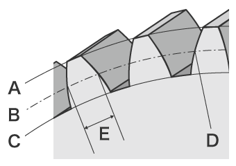
- A
- Addendum circle
- B
- Pitch circle
- C
- Dedendum circle
- D
- Pitch point
- E
- Tooth thickness
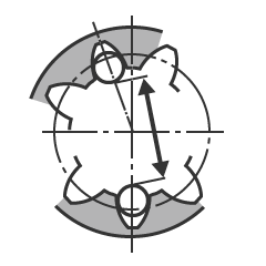
Tooth thickness is the thickness of a single tooth on the pitch circle. Here, we will explain using an example of a spur gear, the most common gear type. The structure of a spur gear is as shown in the figure.
Causes of Changes in Gear Tooth Thickness
Bending load (bending moment), contact pressure, and compressive load are applied to the gear teeth as the gear rotates. When a tooth engages with another part, friction occurs on the tooth surface and causes wear. When tooth thickness changes due to deformation or wear, backlash becomes larger and can cause noise, vibration, or other problems. The loads and wear must be fully considered when gears are used. When hardness is high and the risk of damage due to pitching is low, gear strength is determined by the bending load (bending moment). When hardness is low or when the gear operates for prolonged periods, strength is determined by the tooth surface strength.
Changes in gear tooth thickness resulting from bending load (bending moment)
A large load is applied to gear teeth and is referred to as the “bending load.” Bending load is a load which is applied to a single tooth. When the bending load exceeds the gear tooth surface strength, the tooth deforms.
The load applied to a gear tooth can be understood using “beam theory” from material mechanics. With a cantilever beam, stress concentration occurs at the root of beam, resulting in a large load. In the case of a gear as well, a tooth can be considered to be a cantilever beam, and the load applied to the root is considered a bending load.
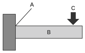
- A
- Fixed
- B
- Beam
- C
- Load
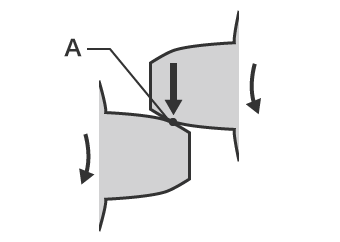
- A
- Pitch point
Bending load can be calculated using the formula below.
M = F × l = σ × Z
- M
- Bending load
- F
- Load
- l
- Total length of tooth
- σ
- Maximum bending stress
- Z
- Cross-section modulus
For reference, the cross-section modulus is the value of tooth surface area divided by six. Maximum bending stress is the value of the bending load divided by the cross-section modulus. Because gears have complex shapes, accurate calculation of strength is not easy. In addition, variation in the load due to the conditions of use must also be considered.
Tooth surface strength
Tooth surface strength is the pressure limit that the tooth surface can endure. Gears contact each other at the pitch points in order to transmit rotation force. When contact between gears occurs, every tooth is repeatedly subjected to a large force, and wear or scratches occur on the tooth surfaces. Small cracks may cause the type of damage called pitting.
To prevent such problems, calculate the strength based on the stress called Hertzian Maximum Contact Stress* that results from contact surface deformation, and obtain in advance the tooth surface strength for the gears that will be used.
* This is the maximum stress applied to elastic contacting parts of two objects such as one spherical surface and another spherical surface, one cylindrical surface and another cylindrical surface, or a spherical surface and a flat surface.
Changes in gear tooth thickness due to wear
When friction with the other part that engages with the gear teeth becomes larger and wear occurs, tooth thickness is reduced and backlash becomes larger. When wear further increases, contamination of the lubricating oil becomes severe. Noise and vibration increase, and the gear temperature rises. The causes of such wear include the following:
- Insufficient strength of gear (tooth surface strength)
- Assembly failure
- Deformation of gear, shaft, or other part
- Lubricating oil defect
Gear wear is referred to the following:
- Polishing
- Fine unevenness is removed from the tooth surface, making the surface smooth like a mirror.
- Abrasive wear
- Irregular linear grooves are formed in the sliding direction on the tooth surface, creating abrasion marks.
- Scratching
- This is one type of abrasive wear. Linear grooves are formed, and the tooth surface looks as it has been dug at with a fork.
- Scoring
- Welding and tearing occur alternately on the tooth surface, resulting in deterioration of the tooth surface.
Problems in Conventional Gear Tooth Thickness Measurements
Conventional methods of measuring tooth thickness include chordal thickness measurement, span measurement of teeth, and over pin measurement, all of which are measured using hand tools. Profile measurement systems and gear measurement systems are also used. However, even for a spur gear, which is the easiest type to measure, measurement requires skill and time. In addition, measurement becomes extremely difficult in the case of gears with complex shapes such as helical gears or bevel gears.
Measurement of gear tooth thickness using hand tools
In conventional tooth thickness measurements using hand tools, the methods used are span measurement of teeth, and over pin (ball) measurement.
- A
- Span of teeth
- Span measurement of teeth
- This tooth thickness measurement method is the most commonly used. A certain number of teeth are held between the probes of measuring tools such as a micrometer in order to measure the length and calculate the tooth thickness for that number of teeth. The measured value may vary depending on the contact conditions of the measuring tool. Because pitch and tooth shape may affect the measurement, multiple measurements must be made around the entire gear periphery, requiring much time.
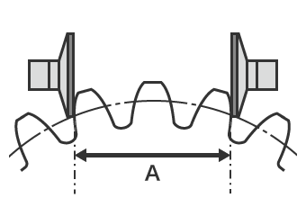
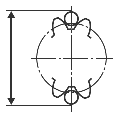
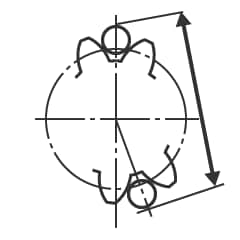
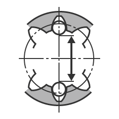
- Over-pin measurement
- This tooth thickness measurement method is also called “ball measurement.” It can be used to measure the tooth thickness of an external gear as well as an internal gear. When measuring, pins or ball are placed into opposite facing tooth grooves (when the number of teeth are even), or into opposite tooth grooves offset by 180/z (°) (when the number of teeth are odd). With an external gear, the tooth thickness is found by measuring outside dimension (over pin dimension). With an internal gear, it is found by measuring the inside dimension (between pin diameter).
Problems in gear tooth thickness measurement using a profile measurement system
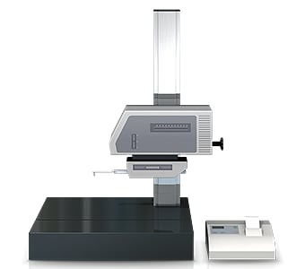
A profile measurement system measures and records the profile of a target by tracing its surface with a stylus. In recent years, profile measurement systems have been developed to use a laser instead of a stylus to measure complex shapes by tracing the profile in a non-contact manner. Some models are even able to perform measurement of both the top and bottom surfaces.
However, with a profile measurement system, it is necessary to acquire accurate measurement lines for the gear teeth.
This involves the following problems:
- Measurement work requires much time, including time for fastening the sample to the jig and levelling it. Knowledge and skills related to using profile measurement systems are also required in order to level a target accurately.
- The stylus of a profile measurement system moves up and down in an arc centred on the fulcrum of the stylus arm; the tip of the stylus also moves in the X-axis direction producing error in the X-axis data.
- Tracing the desired line with the stylus is extremely difficult work, and even slight displacement of the stylus produces error in the measured values.
- It is also difficult to increase the number of targets because of the need to pinpoint specific locations for measurement.
- Only part of a target can be measured, and evaluation of the entire surface is not possible.
Solution to Problems in Measurement of Gear Tooth Thickness
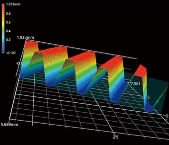
The measuring instruments that are typically used to measure gear tooth thickness involve problems such as the amount of time required to position the target, and the fact that measurement of three-dimensional targets and areas is performed by means of point or line contact. To resolve these measurement problems, KEYENCE has developed the 3D Optical Profilometer VR Series.
The VR Series accurately captures the 3D shape of the entire target surface without contacting the target. It also measures the 3D shape by 3D-scanning the target on the stage in as little as one second with high accuracy. It is capable of instantaneous and quantitative measurement with no errors in the measurement results. This section introduces some specific advantages of the VR Series.
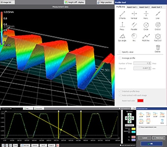
Advantage 1: No variation
A wide range of assist tools can be used to accurately draw perpendicular profile lines on the PC screen at any desired location in the scanned 3D shape data. This eliminates variation in the measurement results. For example, when the cylinder axis tool is used, the measurement line on the gear can be easily and accurately decided without variation.
Once a workpiece has been scanned, its profile (cross-section) can also be measured at locations different from the locations used in past measurement. This eliminates the need to set and measure the same target again and enables comparisons with past data.
The wide variety of assist tools allows simple and intuitive configuration of the desired measurement conditions. In addition to easy configuration, the assist tools allow the system to be operated easily even by novices, making it possible even for operators who are unfamiliar with measurement to perform accurate measurement in as little as one second. This makes it possible to easily increase the number of samples or perform trend analysis for measurement and inspection during commercial production as well as R&D, testing, and evaluation.

Advantage 2: Measure tooth thickness of gears with complex shapes in as little as one second.
The VR Series acquires surface data (800,000 points) for the 3D target shape in as little as one second, dramatically reducing the time required for measuring large numbers of points. It instantaneously and accurately measures the maximum and minimum surface irregularities on the entire target surface of the gear, enabling swift evaluation of the gear based on the preset tolerance.
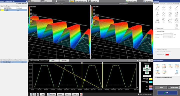
Multiple sets of efficiently collected measurement data can be displayed in lists, and the same analysis contents can be applied to all data sets at the same time.
Shapes of multiple targets can be measured, and the differences in the data can be confirmed at a glance. This makes it possible to easily perform quantitative analysis and evaluation of how much difference there is between an OK part and an NG part.
The VR Series can also perform rapid measurement of the tooth thickness for helical gears and bevel gears, which were previously difficult to measure due to their complex shapes. All measurement results are digitalised, significantly reducing the work required for subsequent data comparison and analysis.
Summary: Dramatic Improvement and Higher Efficiency in Difficult Gear Tooth Thickness Measurement
Previously, measurement of gear tooth thickness took much time, limiting the number of targets which could be measured. In some cases, measurement was not possible at all due to the complex shapes. The VR Series is capable of quickly measuring and quantifying tooth thickness for these shapes as well. This allows the VR Series to be used for more efficient and more advanced evaluation of gear quality.
- Because the entire surface is measured, the VR Series can easily measure a wide area. In addition to tooth surface shape, it can also measure various parameters such as roughness.
- This eliminates variation resulting from human factors, making true quantitative measurement possible.
- Without the need for positioning or other preparation, measurement can be performed simply by placing the target on the stage and pressing a button. This eliminates the need to assign a specialised operator for measurement work.
- 3D shapes can be measured easily at high speeds with high accuracy. This makes it possible to measure a large number of targets in a short time, helping to improve quality.
This system also allows comparisons with past 3D shape data, as well as easy data analysis such as roughness distribution. It can be used effectively for a wide range of purposes including trend analysis of fracture surface characteristics resulting from temperature changes, and checking the fracture conditions.
