

Smart Valve Manifold
SP-N/V series

Valve Unit 2× 3/2-way valve, NC/NC 14 mm ø8 SP-VT14D8
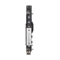
*Please note that accessories depicted in the image are for illustrative purposes only and may not be included with the product.


Specifications
Model | SP-VT14D8 | |||
Type | Valve unit | |||
Valve size | 14 mm | |||
Valve type | 2× 3/2-way valve, NC/NC | |||
Port Size | ø8 | |||
Valve structure | Elastomer seal | |||
Manual operation | Push-turn lock type (driver operation) | |||
Supported fluids | Air *1 | |||
Fluid temperature | -5 to +50°C (no freezing) | |||
Flow rate characteristics | 580 L/min *2 | |||
Response time | 40 ms or less *3 | |||
Maximum operating frequency | 3 Hz *4 | |||
Operating pressure range | With internal pilot | 0.25 to 0.8 MPa | ||
With external pilot | 0.2 to 0.8 MPa *5 | |||
Pressure resistance | 1.0 MPa | |||
Sensor connection port | Connector | M8 (A-code) 4-pin, female | ||
Power supply capacity | 200 mA *6 | |||
Protection circuit | Overcurrent protection circuit | |||
Communication/input | Switchable between CS-Link and control input | |||
CS-Link | Supported models | CS-LxxPC/CS-LA1C/SP-Cxx | ||
Number of connectable devices | CS-LxxPC: Up to 2 units; SP-Cxx/CS-LA1C: Up to 2 units *7 | |||
Control input | Input type | PNP/NPN switchable | ||
Max. number of inputs | 2 *7 | |||
ON voltage | PNP: 15 V or more, NPN: 6 V or less | |||
OFF voltage | PNP: 6 V or less, NPN: 15 V or more | |||
Short-circuit current | 3 mA or less | |||
Protection circuit | Surge protection circuit | |||
Current consumption | Without valve operation: 20 mA or less at 24 V; | |||
Environmental resistance | Enclosure rating | IP65/IP67 (IEC 60529) | ||
Ambient temperature | -5 to +50°C (no freezing) | |||
Relative humidity | Up to 85% RH (no condensation) | |||
Vibration resistance | 10 to 500 Hz; Power spectral density: 0.204 G2/Hz; X, Y, and Z directions | |||
Shock resistance | 100 m/s2 (10 G); 1000 times each for X, Y, and Z axes | |||
Material | Flow path | Polyamide, POM, Aluminium alloy, FKM, HNBR, NBR, Nickel-plated brass / Brass (closed centre, exhaust centre, and pressure centre types only) | ||
Non-flow path | Polyamide, PAR, POM, HNBR, NBR, Aluminium alloy, Zinc-nickel plating, SUS304 | |||
Weight | Approx. 160 g | |||
*1 If air with a low dew point is used as the operating fluid, deterioration of the lubrication characteristics inside the device may affect the reliability (service life) of the equipment. | ||||