Safety Interlock Switches
GS-M series
Specs Safety Interlock Switches GS-M series
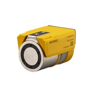
Main Unit for hinged door
|
Model |
GS-M51P |
GS-M51N |
GS-M53P |
GS-M91P |
GS-M91N |
GS-M93P |
|||
|
Image |
|
|
|
|
|
|
|||
|
Type |
For hinged door Small M12 Connector Standard |
For hinged door Small M12 Connector Advanced function |
For hinged door High-holding force M12 Connector Standard |
For hinged door High-holding force M12 Connector Advanced function |
|||||
|
Holding force when locked |
500N |
900N |
|||||||
|
Holding force when unlocked |
Approx. 30N *1 |
Approx. 50N *1 |
|||||||
|
Cascading |
Max. 20 units |
Max. 16 units |
|||||||
|
Operating distance |
Sao(OFF→ON) |
0.1 mm *2 |
|||||||
|
Sar(ON → OFF) |
15 mm *2 |
||||||||
|
Response time (ms) |
Lock→Unlock |
250 ms *3 |
|||||||
|
Unlock→Lock |
|||||||||
|
Detect→ Not detect |
20 ms + 2 ms × (number of cascaded unit -1) *3 |
||||||||
|
Not detect→ Detect |
300 ms + 25 ms × (number of cascaded unit -1) *3 |
||||||||
|
Control output (OSSD output) |
Output |
Transistor outputs × 2 |
|||||||
|
Max. load current |
150 mA |
||||||||
|
Residual voltage (during ON) |
Max. 2.5 V (with a cable length of 5 m) |
||||||||
|
OFF state voltage |
Max. 2.0 V (with a cable length of 5 m) |
||||||||
|
Leakage current |
Max. 0.5 mA |
||||||||
|
Max. capacitive load |
0.8 uF |
||||||||
|
Load wiring resistance |
Max. 2.5Ω |
||||||||
|
AUX (Non-safety related output) |
Output |
Transistor output |
|||||||
|
Max. load current |
50 mA |
||||||||
|
Residual voltage (during ON) |
Max. 2.5 V(with a cable of 5 m) |
||||||||
|
External input (Short-circuit current) |
Safety input |
Approx. 1.5 mA × 2 |
|||||||
|
Reset/EDM input |
Approx. 5 mA |
||||||||
|
Lock control input |
Approx. 2.5 mA |
||||||||
|
OSSD operation switchin input |
Approx. 2.5 mA |
||||||||
|
Applicable Standards (Safety) |
EN61508, IEC61508(SIL3), EN ISO13849-1:2015(PL e, Category 4), |
||||||||
|
Protection circuit |
Reverse current protection, short-circuit protection and surge protection for each output |
||||||||
|
Power supply |
Power voltage |
24 V DC ±20 % (Ripple P-P 10% or less, Class2) |
|||||||
|
Power consumption |
5 W |
6 W |
|||||||
|
Environmental resistance |
Enclosure rating |
IP65/67 (IEC60529) |
|||||||
|
Operating ambient temperature |
-20 to 55°C(No freezing) |
||||||||
|
Operating relative humidity |
5% to 95%RH |
||||||||
|
Storage temperature |
-25 to 70°C(No freezing) *4 |
||||||||
|
Storage relative humidity |
5% to 95%RH |
||||||||
|
Vibration resistance |
10 to 55 Hz, Double amplitude 2.0 mm, |
||||||||
|
Shock resistance |
30 G in X, Y, Z directions 6 times each axis |
||||||||
|
Material |
Main unit |
PBT, PET/PAR, TPC, PC, Nickel-plated steel |
|||||||
|
Actuator |
PBT, SUS304, Nickel-plated steel |
PBT, Painted steel, Nickel-plated steel |
|||||||
|
Mounting bracket |
Aluminum (Plate and screw: Steel) |
||||||||
|
Weight |
Main unit |
Approx.250 g |
Approx.480 g |
||||||
|
Actuator |
Approx.160 g |
Approx.250 g |
|||||||
|
*1 When the actuator is pulled first after unlocked, the holding force increases. |
|||||||||

Main unit for sliding door
|
Model |
GS-ML51P |
GS-ML51N |
GS-ML53P |
|||
|
Image |
|
|
|
|||
|
Type |
For sliding door M12 Connector Standard |
For sliding door M12 Connector Advanced function |
||||
|
Holding force when locked |
500N |
|||||
|
Holding force when unlocked |
Approx. 30N *1 |
|||||
|
Cascading |
Max. 20 units |
|||||
|
Operating distance |
Sao(OFF→ON) |
0.1 mm *2 |
||||
|
Sar(ON → OFF) |
15 mm *2 |
|||||
|
Response time (ms) |
Lock→Unlock |
250 ms *3 |
||||
|
Unlock→Lock |
||||||
|
Detect→ Not detect |
20 ms + 2 ms × (number of cascaded unit -1) *3 |
|||||
|
Not detect→ Detect |
300 ms + 25 ms × (number of cascaded unit -1) *3 |
|||||
|
Control output (OSSD output) |
Output |
Transistor outputs × 2 |
||||
|
Max. load current |
150 mA |
|||||
|
Residual voltage (during ON) |
Max. 2.5 V (with a cable length of 5 m) |
|||||
|
OFF state voltage |
Max. 2.0 V (with a cable length of 5 m) |
|||||
|
Leakage current |
Max. 0.5 mA |
|||||
|
Max. capacitive load |
0.8 uF |
|||||
|
Load wiring resistance |
Max. 2.5Ω |
|||||
|
AUX (Non-safety related output) |
Output |
Transistor output |
||||
|
Max. load current |
50 mA |
|||||
|
Residual voltage (during ON) |
Max. 2.5 V(with a cable of 5 m) |
|||||
|
External input (Short-circuit current) |
Safety input |
Approx. 1.5 mA × 2 |
||||
|
Reset/EDM input |
Approx. 5 mA |
|||||
|
Lock control input |
Approx. 2.5 mA |
|||||
|
OSSD operation switchin input |
Approx. 2.5 mA |
|||||
|
Applicable Standards (Safety) |
EN61508, IEC61508(SIL3), EN ISO13849-1:2015(PL e, Category 4), |
|||||
|
Protection circuit |
Reverse current protection, short-circuit protection and surge protection for each output |
|||||
|
Power supply |
Power voltage |
24 V DC ±20 % (Ripple P-P 10% or less, Class2) |
||||
|
Power consumption |
5 W |
|||||
|
Environmental resistance |
Enclosure rating |
IP65/67 (IEC60529) |
||||
|
Operating ambient temperature |
-20 to 55°C(No freezing) |
|||||
|
Operating relative humidity |
5% to 95%RH |
|||||
|
Storage temperature |
-25 to 70°C(No freezing) *4 |
|||||
|
Storage relative humidity |
5% to 95%RH |
|||||
|
Vibration resistance |
10 to 55 Hz, Double amplitude 2.0 mm, |
|||||
|
Shock resistance |
30 G in X, Y, Z directions 6 times each axis |
|||||
|
Material |
Main unit |
PBT, PET/PAR, TPC, PC, Nickel-plated steel |
||||
|
Actuator |
PBT, SUS304, Nickel-plated steel |
|||||
|
Mounting bracket |
Aluminum, Painted steel (screw: Steel) |
|||||
|
Weight |
Main unit |
Approx.240 g |
||||
|
Actuator |
Approx.130 g |
|||||
|
*1 When the actuator is pulled first after unlocked, the holding force increases. |
||||||

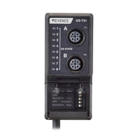
Wiring saving unit
|
Model |
GS-T01 |
|||
|
Image |
|
|||
|
Response time (ms) |
Lock / Unlock |
Response time of GS-M/GS + 110 ms + 70 ms × (number of cascaded unit -1) *1 |
||
|
OSSD |
Response time of GS-M/GS *2 |
|||
|
AUX |
Response time of GS-M/GS + 60 ms + 30 ms × (number of cascaded unit -1) |
|||
|
AUX (Non-safety related output) |
Output |
Transistor output × 8 |
||
|
Max. load current |
20 mA |
|||
|
Residual voltage (during ON) |
Max. 2.5 V (with a cable length of 2 m) |
|||
|
Lock control input |
Approx. 2.5 mA×2 |
|||
|
Protection circuit |
Reverse current protection, short-circuit protection and surge protection |
|||
|
Power supply |
Power voltage |
24 V DC ±20 % (Ripple P-P 10% or less, Class2) |
||
|
Power consumption |
0.8 W |
|||
|
Environmental resistance |
Operating ambient temperature |
-20 to 55°C(No freezing) |
||
|
Operating relative humidity |
5% to 95%RH |
|||
|
Storage temperature |
-25 to 70°C(No freezing) |
|||
|
Storage relative humidity |
5% to 95%RH |
|||
|
Vibration resistance |
10 to 55 Hz, Double amplitude 2.0 mm, 5 minutes in each of the X, Y, and Z directions (IEC 60947-5-3) |
|||
|
Shock resistance |
30 G in X, Y, Z directions 6 times each axis (IEC 60947-5-3) |
|||
|
Material |
Case: PBT Cable:PVC |
|||
|
Weight |
Approx. 290 g |
|||
|
*1 When using the GS-71PC, the response time from "Unlock" to "Lock" increases by 200 ms per unit. |
||||
Mounting brackets
|
Model |
GS-MB11 |
GS-MB12 |
GS-MB13 |
GS-MB21 |
GS-MB22 |
GS-MB23 |
GS-MB31 |
GS-MB41 |
GS-MB42 |
GS-MB43 |
|||
|
Image |
|
|
|
|
|
|
|
|
|
|
|||
|
Type |
Hinged door |
Sliding door |
Hinged door |
||||||||||
|
Applicable model |
for GS-M5 Series |
for GS-M9 Series |
for GS-ML5 Series |
||||||||||
|
Frame size |
30 - 40 mm |
40 - 45 mm |
30 - 40 mm |
40 - 45 mm |
30 - 40 mm |
30 to 40 mm |
40 to 45 mm |
||||||
|
Weight |
Approx. 120 g |
Approx. 110 g |
Approx. 130 g |
Approx. 85 g |
Approx. 120 g |
Approx. 90 g |
Approx. 270 g |
Approx. 140 g |
Approx. 210 g |
Approx. 150 g |
|||